| Japanese | English |
Design Specification
1. Noise Cancelling Algorithm[1]1-1. Specter Subtraction Method (SS Method)
1-2. MAP method using Variable Speech Distribution
1-2-1. MAP Estimate Method
1-2-2. Speech spectrum distribution proposed by T.Lotter and P.Vary
1-2-3. Variable Speech Distribution
2. Implementation of the Noise Cancelling System
2-1.Separating into the Hardware and the Software
2-1-1.Features of the HW and the SW
2-1-2. Feature of Noise Cancelling System
2-1-3. Architecture
2-2. Hardware
2-2-1. Processing flow
2-2-2. Circuit structure
2-2-3. HW timing
2-3. Software
2-3-1. Source code
2-3-2. Flow chart
3. Development Environment
3-1. Hardware Design Process
3-1-1. Design Hardware Logic
3-1-2. Manual of Xilinx ISE and EDK
3-2. Software design process
4. Contest Design Target
5. SPEED and AREA
6. References
7. Download
17th LSI Design Contests・in Okinawa Design Specification - 3-1
3-1. Hardware Design Process
In this section, we describe about process of development. However, this process is a one of example. There are many methods to design hardware circuit, so please research other method, if you don’t use this method.
3-1-1. Design Hardware Logic
In this part, we describe about model-base RTL design using Simulink, and we describe how to lap file into edf file.
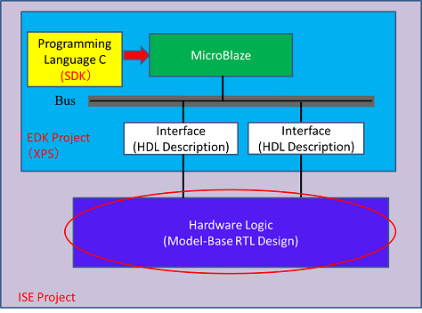
Figure 21
1. We first start MATLAB software, next start Simulink tool on MATLAB. On top menu, we open design
screen to select “File” -> “new file”, after done it, Simulink library browser is started.
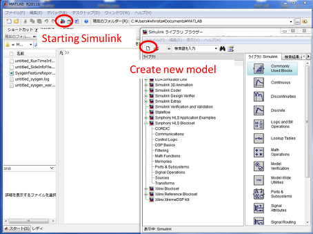
Figure 22
2. We can design HW circuit to select block which you want to use in library, and drag-and-drop that block
into design screen. In this time, we plan to synthesize circuit by using Synplify, therefore we select
Synphony HLS Blockset to design circuit.
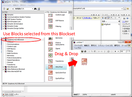
Figure 23
3. After we designed a circuit, we use SHLSTool block of HLS Blockset to create HDL file (.v or .vhd).
Please do following process to create HDL file. Double-click SHLSTool, open the implementation screen,
and we decide implementation target device ‘s information in this screen.
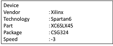
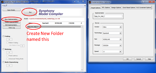
Figure 24
4. Disable Generate “Clock-Reset Circuit” of Clock Reset Options tab..
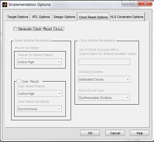
Figure 25
5. Please select the “Asynchronous” in Flip Flop Reset Sensitivity of Design Option tab.
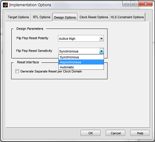
Figure 26
6. We save setting parameter, and after that, we run that file. Then the Folder which include implemented
file is created on MATLAB current folder.
*It is possible to download the created Model file (here) from this folder.
1. Wake the Synplify Preminer. Select “File” → “Open” in top menu. Open the project file (fpga_hw_impl_1
\verilog\fpga_hw.prj) created by SHLSTool, in the folder of Verilog. Click “Implementation Options”on the
left side of screen.
2. Crick the “Implementation Options” in left menu.
3. Check the “Disable I/O Insertion” → Check the “OK”.
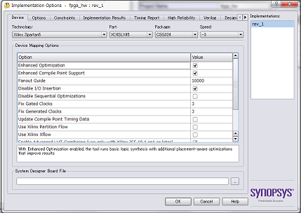
Figure 27
4. Execute (select the “Run”). The file, “rev_1”, is created in “.fpga_hw_impl_1\verilog”. The .edf file is
created in the file, “rev_1”.
5. Crick the “HDL-Analyst” → “RTL” → “Hierarchical View” in top menu.
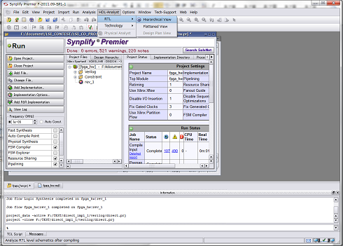
Figure 28
6. We can show the created circuit structure of the .edf file.
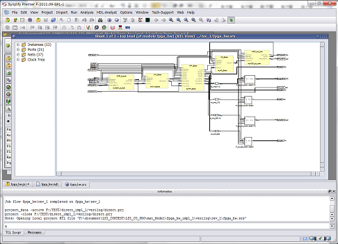
Figure 29
*We can download the created .edf file (here) from this folder.
Please contact me from here if you want the RTL source.
3-1-2. Manual of Xilinx ISE and EDK
AC97 is attached to ATLYS board. To use “AC97 AUDIO CODEC”, the development is used “Atlys_AC97_EDK_demo” which is demo project to control AC97 by MicroBlaze. This demo can be downloaded from ATLYS’s HP. In order to run this demo, EDK later
versions of ISE13.2 is required. The following shows the execution procedure.
1. Unzip the Atlys_AC97_EDK_demo.zip.
2. Start the xps (Xilinx Platform Studio) that is a tool of EDK.
3. Select “File”?”Open project” from the menu at the top of the screen. Next Select “system.xmp” in the
project folder under the “Atlys_AC97_EDK_demo folder”.
4. Click “Hardware”?”Generate Netlist” from the menu at the top of the screen.
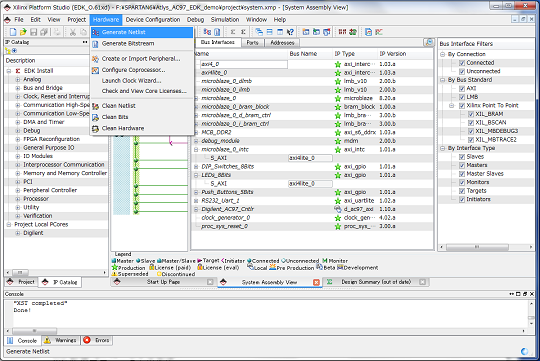
Figure 30
5. After completing implementation, select “Project”?”Export Hardware Design to SDK” from the menu at
the top of the screen.
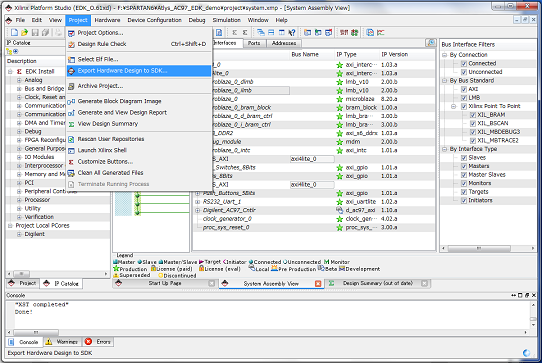
Figure 31
6. Select the “Export & Launch SDK”.
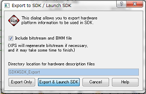
Figure 32
7. Create a folder “SDK_Work” under the folder “SDK_Work Atlys_AC97_EDK_demo\projects \SDK”, and set
it as workspace. Next click “OK”.
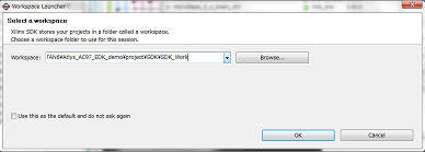
Figure 33
8. SDK is launched. Select “File”?”New”?“Xilinx C Project” from the menu at the top of the screen.
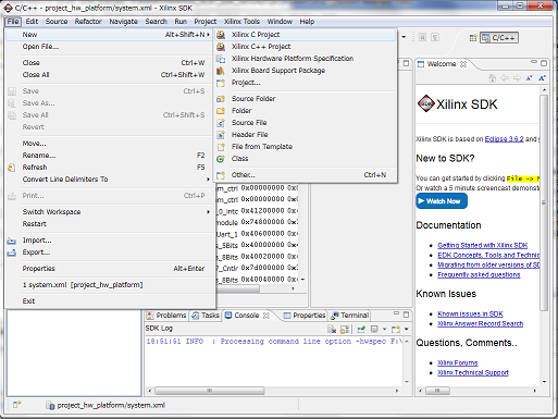
Figure 34
9. New Project is opened. Select the “Empty Application” from the field “Select Project Template”. Next
select ”Next”.
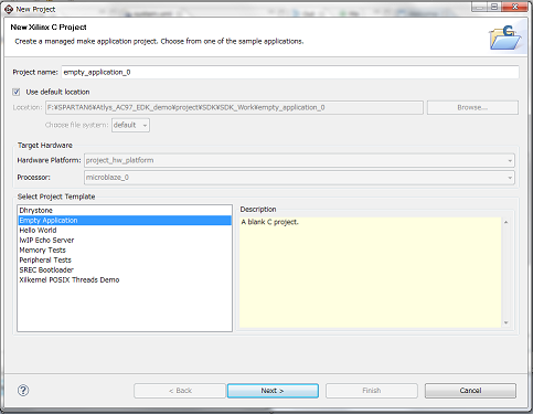
Figure 35
10. Look see that the “Create a new Board Support Package project” has been selected, and click “Finish”.
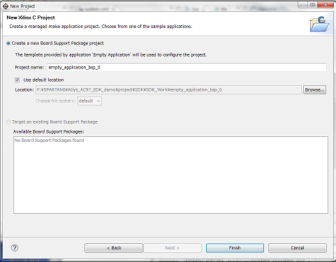
Figure 36
11. Folder “BSP project” and “project C” is added to the "Project Explorer".
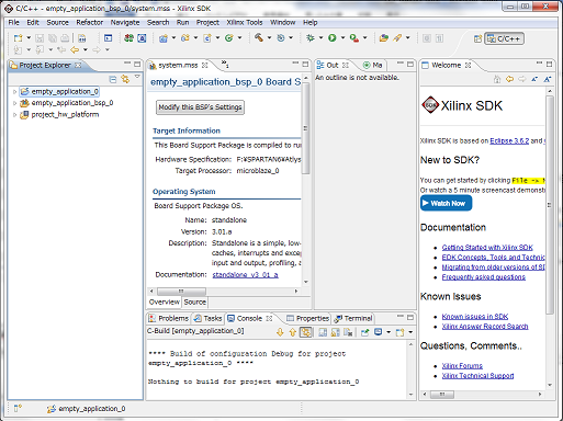
Figure 37
12. Copy all files in “Atlys_AC97_EDK_demo\source\” to “
Atlys_AC97_EDK_demo\project\SDK\SDK_Work\empty_application_0\src”. After that, right click in
“Project Explorer”, and select ”Refresh”. Then the Project is updated ,and source is added in the
“Project Explorer”.
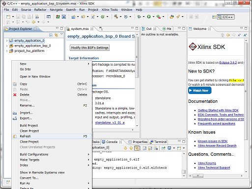
Figure 38
13. Select “Build All” from the “Project” menu at the top of the screen.
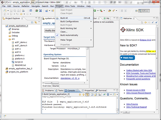
Figure 39
14. Turn on the Atlys, and insert to the connector to PROG port. Select the “Program FPGA” from “Xilinx
Tools” in the menu at the top of the screen.
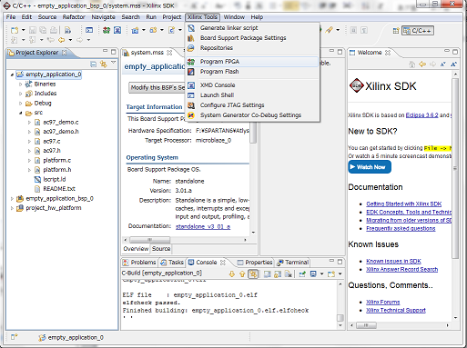
Figure 40
15. Select the file to be written.
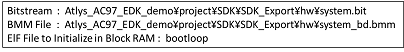
After Selection, click the “Program”. Then the file is written to FPGA.
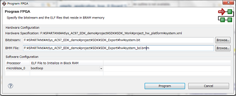
Figure 41
16. Expand “empty_application_0” in “Project Explorer”, and right-click the item “empty_application_0.elf”
from “Binaries “. Select “Run As”?”Launch on Hardware”, and source code is written to the FPGA.
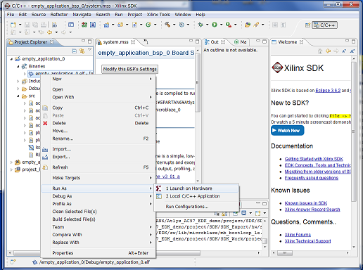
Figure 42
Because HW part and MicroBlaze are cannot connected for demo project, the ISE is needed to setup.
1. Launch ISE. “New Project Wizard” is launched when select the “File“?”New Project” from the menu at
the top of the screen.
2. In page of the “Create New Project”, set the project name and location of the save folder.
After you verify the Top-level source type is set to HDL ,and click “Next”.
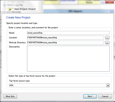
Figure 43
3. In page of the “Project Settings”, set up the target device and development tools. Set as shown, and
then click “Next”.
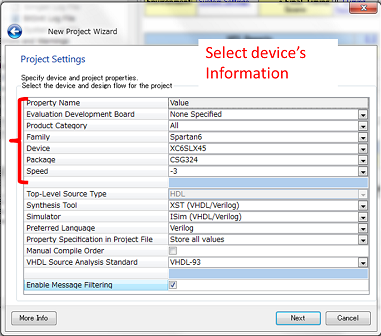
Figure 44
4. In page of the Project Summary, Click the “Finish” after checking the setting error. After that, close
“New Project Wizard”.
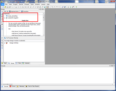
Figure 45
At this point, empty project of ISE is created.

Figure 46
In the foregoing paragraph, you generated an empty ISE project. Next, you should add an EDK project (system.xmp) to the ISE project (noise_cancelling.xise). The procedures are as follows.
1. You should copy Atlys_AC97_EDK_demo\project folder into the folder of ISE project. We changed the
name of this folder to Demo this time.
2. You should start ISE project, and click Project → Add Source from a menu of the upper part of the
screen. You should choose system.xmp in the Demo folder which you copied just now.
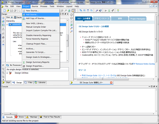
Figure 47
3. You will be able to confirm that EDK is added to ISE project.
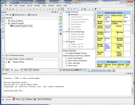
Figure 48
As a result, you can connect the HW part that is designed on ISE and the circuit of the EDK project.
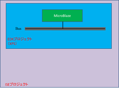
Figure 49
You add interface for the outside of the EDK project circuit in XPS to connect the HW part to a CPU. We will explain about how to connect on ISE in the next clause (Integration of HW circuit at the ISE).
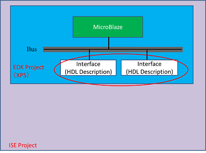
Figure 50
1.You should click the system in Hierarchy of the ISE, and XPS will starts when you choose Manage
Processor Design (xps) from Processes.
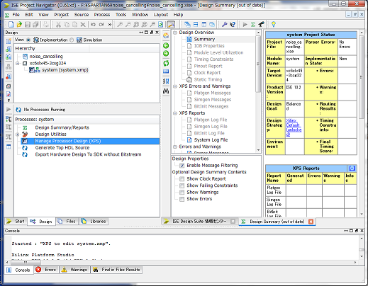
Figure 51
2. You should make the peripheral in reference to
"Create and Import Peripheral For Microblaze ver AXI.ppt(here)".
3. You should right-click on the IP which you want to add from IP Catalog column, and click on Add IP to
add a peripheral.
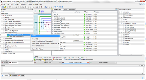
Figure 52
4. The setting window should be displayed, depending on your choice of IP, so you set it.
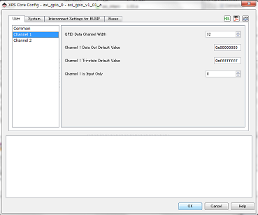
Figure 53
5. The peripheral should be added. When you want to change setting, you should right-click and click
on Configure IP. It is deleted by Delete Instance.
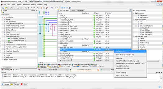
Figure 54
6. You can set the the connection setting of the peripheral in the Ports tab. The port of the peripheral is
displayed when you open the peripheral which you want to set the connection setting. When there is the
port which you want to connect in XPS, you should set connection from New Connection or choices.
If you want to connect in outside of XPS project, you should choose Make External.
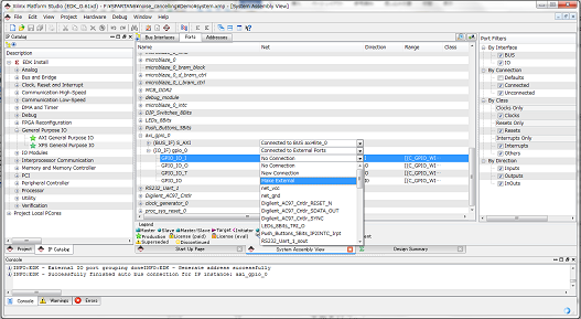
Figure 55
7. If you chose Make External, it is added to the item of External Ports.
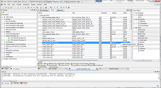
Figure 56
8. In this case, we use the test IP which we made in cause 2. First, you should add six test IPs, and change
the name as follows.
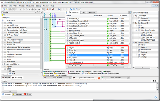
Figure 57
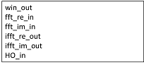
9. You should set the port in reference to cause 6〜7.
win_out, ifft_re_out, ifft_im_out sets the following ports as External Ports.
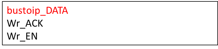
HO_in, fft_re_in, fft_im_in sets the following ports as External Ports.

10. If you finished to design in XPS, you should choose Hardware → Generate Netlist in the menu of the
upper part of the screen and generate the netlist.
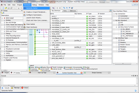
Figure 58
11. You should close the XPS.
12. You should click system in Hierarchy of ISE and choose Generate Top HDL Source from Processes.
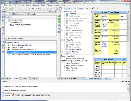
Figure 59
13. system_top.v should be generated. This file is generated in Demo folder. You should copy this in the
folder of the ISE project.
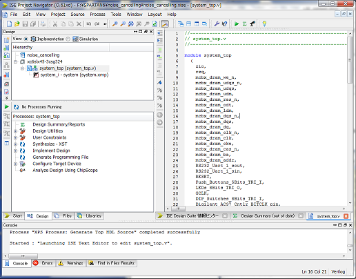
Figure 60
14. You should right-click on system_top.v of the Hierarchy, and exclude it from a project by “Remove”.
After that, you should add the system_top.v file under the ISE project folder in Add Source. This
system_top module becomes the top module of the system which you develop.
We connect HW circuit which you made in section 3-1-1. and the circuit in XPS which you made in the foregoing paragraph on ISE.
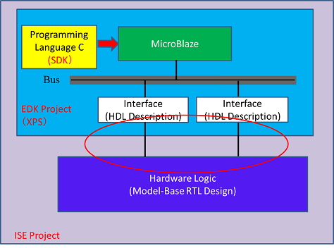
Figure 61
1. We copy edf file which you made in symphony to ISE project folder, and we add it to the project by Add
Source.
2. Describe the module of this circuit(Model-Base-RTL design) into system_top.v by verilog, and connect it
and the port of the circuit which you made in XPS project.
We can download the circuit time of the top module(here) which we make in this time from here.
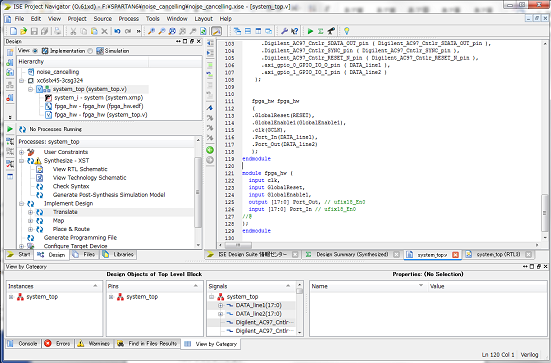
Figure 62
3. We can check the circuit structure in View RTL Schematic in Synthesize-XST or Processes tab.
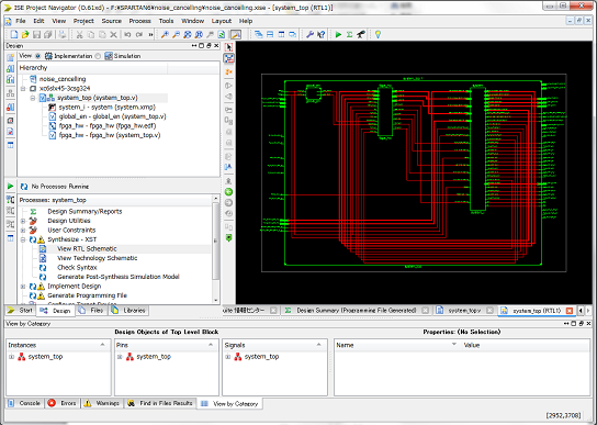
Figure 63
1. We select system_top in Hierarchy, and right-click Generate Programing File in Processes tab, and run
Rerun All.
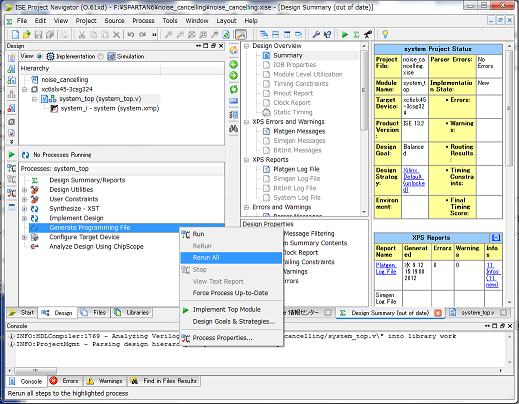
Figure 64
2. If there is no error, system_top.bit is created in ISE project folder.
Completed implementation of HW.