
Design Specification
1.Small RISC Processor
(SRP) architecture
5.Instruction ROM and
Data Memory
BASIC
FREE
12th LSI Design Contests・in Okinawa Design Specification - 9
10.Design Task Level 1: BASIC
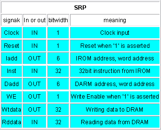
In this design level, design SRP as shown in figure 7. Then execute the Bubble sort to verify your design. Table 9 indicates the input output port signals.
Table 9: pin list for Level1
11.Design Task Level 2: FREE
You can freely expand the SRP spec such as
1) pipeline operation,
2) more instructions,
3) and more.
12.SPEED and AREA
Since it is impossible to use the same synthesis library for various participants,
* use 1 exor gate delay as a 1 UNIT_DELAY for speed comparison and,
* use 1 exor gate area as a 1 UNIT_AREA for area comparison.
How to measure 1 exor gate delay
1. Synthesize the 50 inputs exor gate
2. Measure the total delay time
3. UNIT_DELAY is obtained by total delay divided by the number of stages
4. UNIT_AREA is obtained by the total area divided by number of EXOR gates
* VHDL code for 50 inputs exor : parity.vhd
* example of synthesized circuit :PDF,PS
* example of critical path delay measurement :report_timing
* example of circuit area measurement :report_area
In the previous example, total delay = 7.17 ns and 6 circuit stages, then the 7.17/6= 1.195 ns is the UNIT_DELAY of the speed. Please normalize your circuit speed by this UNIT_DELAY.
In the example, total cell area = 147.0 and 49 EXOR gates. Then 147.0/49=3.0 is the UNIT_AREA. Please normalize your circuit area by this UNIT_AREA.