Design Specification
1.Small RISC Processor
(SRP) architecture
5.Instruction ROM and
Data Memory
BASIC
FREE
12th LSI Design Contests・in Okinawa Design Specification - 2
2.Supported Instructions
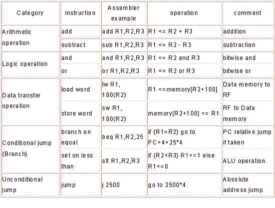
The supported nine instructions are summarized in Table 1. Those instructions are categorized into Arithmetic, Logic, Data transfer, conditional jump (branch), unconditional jump operations.
Table 1 Supported Instructions

In the Table 1, Rn indicates register file and its address of n. The R1 means address=1 of register file. In SRP, there are 32 of 32 bit registers. Then address of register file is 0 to 31 such as R0 to R31.
Note] SRP also follows to typical RISC architecture. Then, R0 is special register. R0 cannot be written and R0 is always 32bit 0’s since the value of 0 is used frequently in a program.
Operation of “R1<= R2+R3” is shown in the Table 1. This means that the contents of R2 and R3 are read out from register file and mathematical operation + is performed in ALU. Then the result of ALU will be written in R1 location. So do other operations such as -, and , or, slt.
Load word instruction “lw” transfers 32 bit data from data memory to register file. Instruction of “lw R1, 100(R2)” does the following operation.
1) Content of R2 and integer 100 indicated in the instruction will be added to generate memory address.
2) The calculated memory address is used to read the data memory.
3) The data will be written onto the R1.
Instead, store word instruction “sw” transfers 32 bit data from register file to data memory. This is reverse data transfer of “lw”. Instruction of “sw R1, 100(R2)” does the following operation.
1) Content of R2 and integer 100 indicated in the instruction will be added to generate memory address.
[same as lw]
2) R1 data will be read out.
3) The calculated memory address is used to write the R1 data onto data memory.
Branch on equal “beq” operation will compare the contents of two register file location. Then if those are the same (result of subtract operation is 0), branch to the indicated address of instruction memory.
As already explained before, program counter PC indicates the address of executing instruction. Usually, instructions in memory executed sequentially. Addressing of the computer memory is typically 8bit (byte) address. Since SRP uses 32bit width instruction (explained later), four address location is needed to store one instruction. Then, the address of next instruction is address of current instruction (PC) + 4.
Let’s go back to the explanation of beq. Instruction of “beq R1,R2,25” means compare R1 and R2. If the result is the same, next instruction address will be modified from PC+4 to PC+4+25*4. This integer 25 is indicated in the instruction. This means branch to 25 more ahead instruction. As already explained, one instruction possesses 4 address locations then 4 times multiply operation is used. In addition, the negative integer in the instruction means branch to previous address.
Instruction of “slt R1,R2,R3” does the following operation. If R2 Finally, un-conditional jump operation is explained. Recall “beq” and the destination address (address to be used when branch operation is taken) is PC+4+integer. Since the destination is determined by relatively to PC, we call this beq is PC-relative jump. However, in instruction of “j 2500”, the destination is not relative to PC but absolute memory address such as 2500*4. The integer value 2500 means 2500th instruction from address=0. Then, the absolute memory address will be 2500*4=10000.
