The 13th Design Contest in Okinawa・ Design Specification- 7
7. Timing diagram of the system
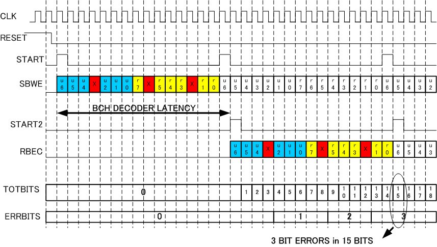
Figure9 : Timing Diagram of System
Figure 9 shows the timing diagram of the system. After de-assertion of RESET signal, ENCODER generates START and SBWE signals. Every 15 cycle is one BCH(15,7) packet data. DECODER received SBWE signal and perform error correction to generate RBEC signal which includes both information and parity. TOTBITS signal is total received bits and ERRBITS is the number of error bits received.
Copyright (C) 2009 Radrix. All Rights Reserved.