13th LSI Design Contests・in Okinawa Design Specification - 3
3.BCH encoder circuit example
Figure 2 show the encoder circuit example. SIN input port receives information bits from u6, u5, … down to u0. During this input sequence, the switch is connected to A terminal in order to pass those u6, …, u0 signal to the output SB port and to the shift registers. Since the U(x)*x8 mod G(x) is calculated, eq (6) is used to reduce the power of the polynomial.
 … (5)
… (5)
 … (6)
… (6)
Eq (6) means that if the coefficients of x8 = 1, coefficients of 0, 4, 6, 7th will be exored with ‘1’. The circuit in figure 2 performs this operation. Consequently, after inputting all u6, …, to u0 to the registers, remainder will be calculated. Then after, the switch is connected to B terminal, remainder r7, …, r0 will be shifted out to SB terminal. The detail operation is shown in figure 3.
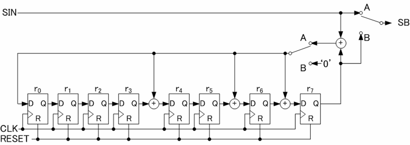
Figure 2: Circuit example of ENCODER
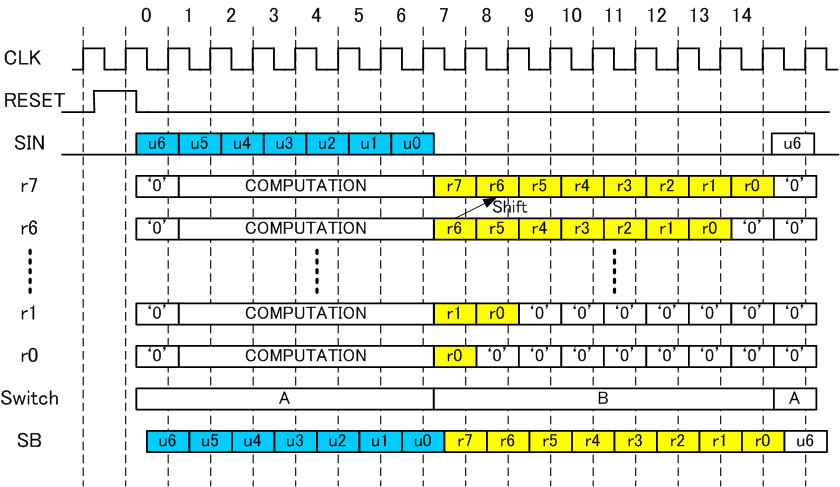
Figure 3: Timing diagram of encoder operation
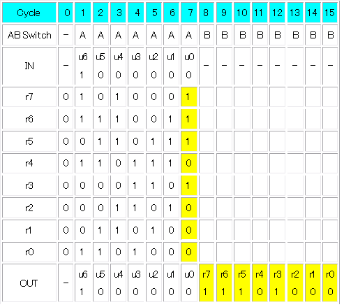
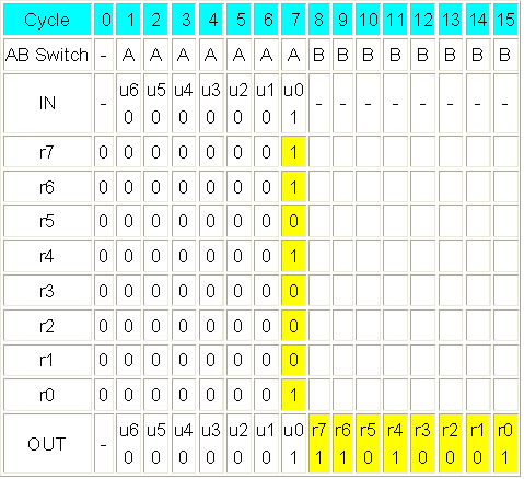
In table 3 and 4, two cases of register values are shown as example. The one corresponds to information bits = {0, 0, 0, 0, 0, 0, 1}, the other corresponds to information bits = {1, 0, 0, 0, 0, 0, 0}.
Case 1: information bits = {0, 0, 0, 0, 0, 0, 1}
In case 1, u0 =1. Then according to eq (6), r7=r6=r4=r0=1.
… (6)
Since this operation happens in cycle 7 (last cycle of switch A period), the values are just shift out at the cycles from 8 to 15 as shown in table 3.
Table 3: encoder operation when information bits = {0, 0, 0, 0, 0, 0, 1}
Case 2: information bits = {1, 0, 0, 0, 0, 0, 0}
In this case, u6=1 means the coefficient of x14 is 1. Then eq (6) operation performed at cycle=1 and 6 cycle shift operation is performed after that.
… (6)
This processing can be understood as eq (8) operation.
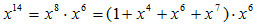 … (8)
… (8)
Detail operation will be explained step by step as follows.
Detail operation will be explained step by step as follows.
Cycle=2: By shift operation, r7, r5, r1 will be 1. In addition overflow (previous r7=1) = 1 and u5=0 are exored to generate ‘1’. This ‘1’ goes to r7, r6, r4 and r0 to perform exor operation.Consequently, r7=0, r6=r5=r4=1, r3=r2=0, r1=r0=1.
Cycle=3: u4=0 and overflow (previous r7=1) =0. Then no feedback operation will be performed. Then shift operation only performed.
Table 4: encoder operation when information bits = {1, 0, 0, 0, 0, 0, 0}