| Japanese | English |
Design Specification
1. Purpose2. Design enviroment
3. Principle
3-1. CORDIC method
3-2. Extension to \(-π〜π\)
3-3. Algorithm
4. Design
4-1. Design of the updated
value \(α_i\) and \(δ_i\)
4-2. Judgement of the angle \(z\)
by the angle \(θ\)
4-3. Determination of the
initialvalue \(x_0\)
4-4. Output example of the
value
5. Example to Level2
6. Challenge
7. Unit of measurement of the
circuit scale and speed
18th LSI Design Contests・in Okinawa Design Specification - 6
6.Challenge
Upload the v file to be used in basic challenges.
Cordic v-files:Cordic_v.zip
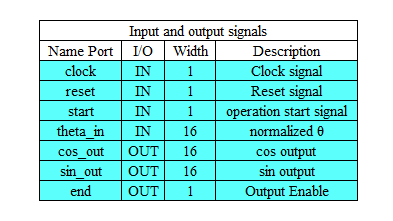
The basic challenges Have done the design of CORDIC circuit that meets the input and output specifications as shown in Table 6-1. It is good even if I have used the uploaded v file regarding CORDIC circuit. Of course, it is fine even without using the v file. It will be the challenge of am thinking the value of the ROM of among the circuit. As input the theta in this CORDIC circuit, making it the circuit to output \(sinθ\) and \(cosθ\).
Table 6-1: input and output specifications
In addition, CORDIC circuit to be uploaded you have to have the following pin placement.
Table 6-2: basic challenge for the pin list
Please indicate the estimated CLK using the Synplify Pro or Xilinx ISE® WebPACK™. Please be greater than or equal to 100MHz for clock frequency.
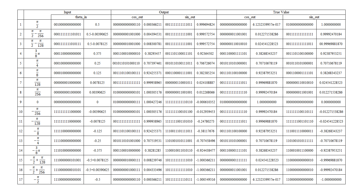
Upload a CORDIC circuit that it is using a 16bit fixed point, and shows the detail in Table 6-1, we are visually displayed in Figure 6-1.
Table 6-3: 16bit fixed point
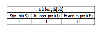
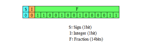
Figure 6-1: 16bit fixed point
I'll explain with respect to the input of the CORDIC circuit. You can use the value of C programs that are uploaded by 3-3 algorithm with respect to the input. When you run the program, it displays the value of \(θ\) you want to find in binary and decimal. Please refer to the binary value obtained when the the input of the CORDIC circuit.
Respect CORDIC circuit, source of algorithm description using the VHDL has been published in the following pages.
Please have all means to reference those who are creating the code in VHDL is.
http://www.ie.u-ryukyu.ac.jp/~wada/vlsi14/CORDIC_ALGO.vhd
Source code: Prof. Kazuhisa Wada, University of the Ryukyus
In free challenge, have them create a trigonometric function circuit using a variety of algorithms, as introduced in Chapter 5. Also to satisfy the input and output specifications of Table 6-1 in Level2, that case, please sure to meet the following 8bit of precision decimal point.
If you are more available, please implement an application that uses the trigonometric function circuit that you created.
Required Decimal 8bit accuracy
Importance Circuit size, Latency, Other their circuit evaluation, such as appeal, and operation video, etc.
If you are satisfied with the decimal 8bit accuracy, we evaluate as a challenge of Level2.