| Japanese | English |
14th LSI Design Contests・in Okinawa Design Specification - 4
4. 2D-DCT HARDWARE ARCHITECTURE
Here we introduce 1D-DCT Architecture as an example. Referring to Equation 5, we can draw the architecture as shown in Figure 5. The rectangle means multiplication and circle means adder. The label inside the square means those data has to be multiplied by coefficient defined in Equation 5.
If you have another method or architecture, it would be very good. You must be able to optimize the hardware implementation by reducing the number of multiplier or adder. The lower number of adder or multiplier is better, since we can save a lot of area and power. You can also find the best multiplier to optimize the circuits.
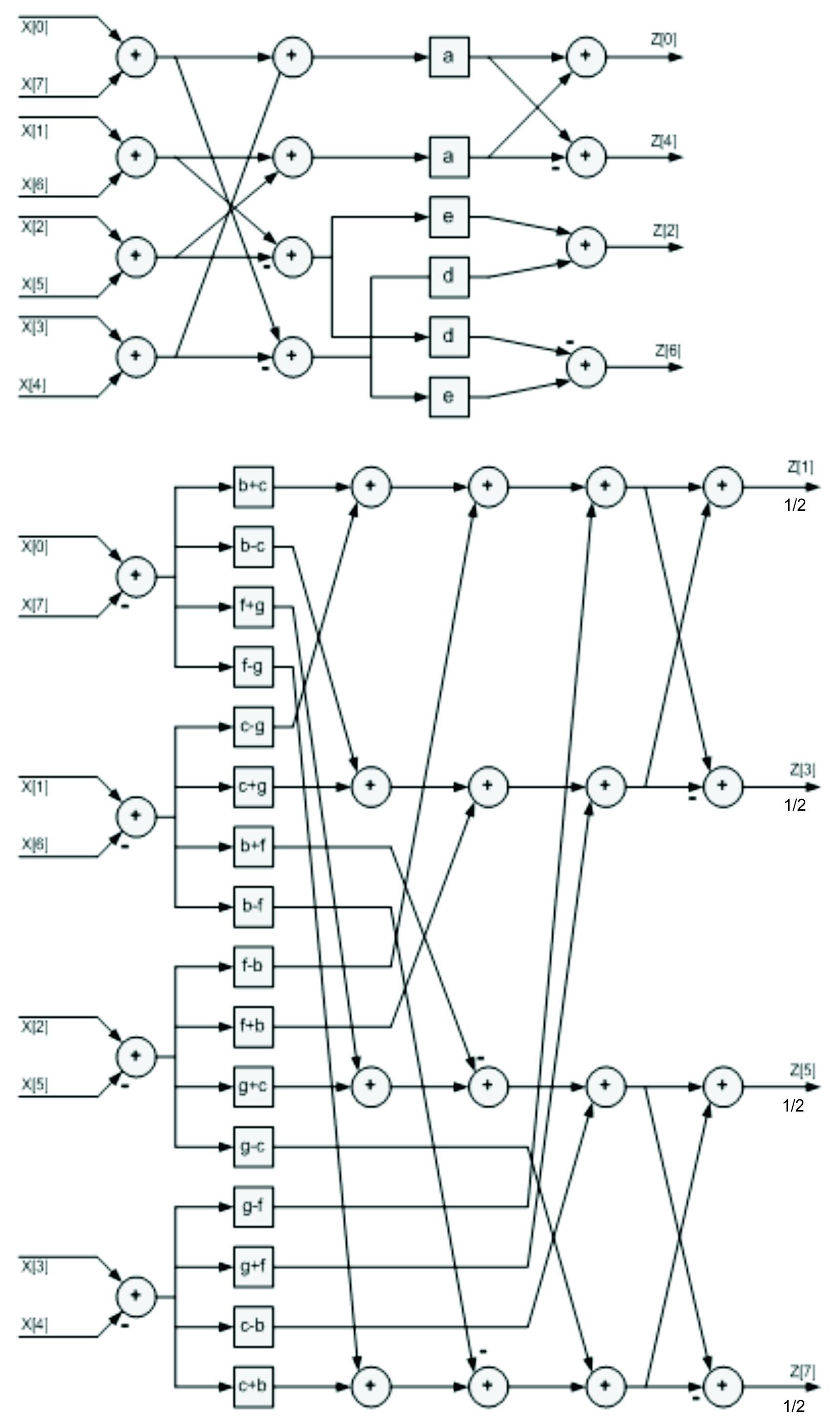
Figure 5 The 1D-DCT Architecture
The first 1D-DCT receives matrix input in row-wise order. Transposition Buffer receives row-wise results and give column-wise input to the second 1D-DCT as depicted in Figure 6.
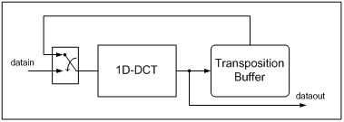
Figure 6. The 2D-DCT Architecture